Assembling your LEM meat grinder correctly transforms an intimidating box of parts into a reliable processing powerhouse that will serve you for decades. Whether you’re a hunter preparing for your first deer season or a homesteader expanding your food preservation skills, proper assembly forms the critical foundation for smooth operation and consistent results. LEM Products has engineered their Big Bite series with intuitive connections and clear specifications that make assembly manageable even for beginners—when you know exactly which parts to use and in what sequence. This guide cuts through the confusion by providing specific, model-based assembly instructions that ensure your grinder performs optimally from day one, eliminating common mistakes that lead to poor grinding, component damage, or safety hazards during use.
With over 1,300 products available through 3,500 retail locations across North America, LEM has earned its reputation as the definitive leader in meat processing equipment since 1990. Their Big Bite series represents the gold standard for home processors, spanning from the #5 and #8 models suitable for moderate use to the heavy-duty #12, #22, and #32 grinders designed for serious game processing. Understanding which model you own determines every aspect of your assembly process—from handle screw threading specifications to compatible replacement parts—making accurate identification the essential first step before touching any components.
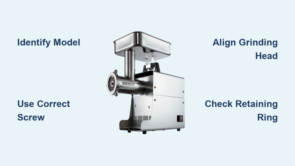
Confirm Your Exact LEM Grinder Model Before Assembly

Avoid costly mistakes by positively identifying your LEM grinder model using the identification plate attached to the motor housing. The Big Bite series includes models 1777, 1779, 1780, 1781, and 1782, where the numerical designation indicates throat size and processing capacity rather than a simple model sequence. Smaller #5 and #8 Big Bite Grinders (models 777, 777a, 779, and 779a) serve home processors with moderate volume needs, while the #12, #22, and #32 models (780, 781, 782, 1780, 1781, and 1782) handle heavier demands with larger components.
Pay special attention to production dates for compatibility. For example, the #1780 Grinder Head explicitly specifies compatibility only with units manufactured in 2017 and newer. If your grinder is used or has been in storage for years, verify the manufacture date against current specifications to prevent compatibility issues. LEM’s customer service can confirm compatibility details when provided with your complete model number and production date—this quick verification saves hours of frustration during assembly.
Why Model-Specific Hardware Matters for Assembly
LEM meat grinders require specific fasteners that vary according to size, directly impacting assembly success and operational safety. The handle attachment system represents the most size-dependent component, with threading specifications that differ between smaller and larger Big Bite models. For #5 and #8 Big Bite Grinders, use the M5 – 0.8 x 15 Handle Screw ($3.99), while the larger #12, #22, and #32 Big Bite Grinders require the M6 – 1.0 x 15 Handle Screw ($3.99).
Beyond the handle screw, verify these critical components against your model’s parts list:
– The Stainless Auger Stud ($6.99 for #5 BigBite Grinders) screws into the auger’s rear extension
– The Retaining Ring ($24.49) for #8 Leonardi Grinders (model 535)
– The Stainless Retaining Ring ($59.99) for #32 Big Bite Grinders
Having all required hardware organized and verified before beginning assembly prevents frustrating interruptions and ensures proper torque specifications can be followed.
Install the Handle with Correct Torque Specifications
The handle attachment provides the mechanical interface between you and the grinder, enabling proper meat feeding while maintaining safe hand positioning. Start by threading the appropriate Handle Screw into the motor housing’s rear extension by hand to ensure proper thread engagement—forcing it with tools risks cross-threading that can damage the aluminum housing.
Once started, tighten with an appropriate wrench to hand-tight plus approximately one-quarter turn. Avoid overtightening, as excessive force can strip the threaded insert in the motor housing—a costly repair that proper technique easily prevents. The handle then slides onto the installed screw and secures with the provided washer and locking nut. Verify handle security by attempting to rotate it in both directions; any movement indicates insufficient tightening that must be addressed before proceeding.
Critical Warning: Handle Screw Compatibility
Using the wrong handle screw size creates immediate assembly problems. If your #12 or larger grinder handle feels loose after installation, you’ve likely used the smaller M5 screw designed for #5 and #8 models. Remove the screw completely, inspect the threads for damage, and reinstall with the correct M6 specification. Cross-threading often creates an initial sensation of tightness that gradually loosens during use—this false security leads to dangerous handle detachment during operation.
Assemble the Grinding Head with Precision Alignment

Begin by washing all grinding head components with warm soapy water, rinsing completely, and drying thoroughly to remove manufacturing residues. For #12 Grinder Heads (model 1780, 2017 and newer), the stainless steel construction provides corrosion resistance but still requires this essential cleaning step before first use.
Mount the grinding head to the motor housing by aligning keyway features and rotating until it seats fully against the motor face. Some models use a bayonet-style mount while others employ threaded connections—consult your specific documentation for exact procedures. Once properly seated, hand-tighten the retention mechanism (typically a large retaining ring) to secure the grinding head against the motor. Final tightening occurs after all internal components are installed and verified for proper alignment.
How to Verify Correct Grinding Head Position
When properly seated, the grinding head should sit flush against the motor housing with no visible gaps. If you notice uneven spacing or hear grinding noises during initial operation, the head isn’t fully seated. Remove and realign the components, ensuring any keyway features mate completely. A grinding head that isn’t fully seated puts excessive stress on the auger and motor, leading to premature wear and potential component failure.
Configure the Auger, Knife, and Plate System Correctly
Begin by threading the Stainless Auger Stud fully into the auger’s rear extension until snug. Apply a small amount of food-grade lubricant to the threads before installation to prevent galling. The cutting knife then attaches to the auger stud’s forward face with its sharp edge facing outward toward the grinding plate—this orientation is critical for proper cutting performance.
Common Knife Installation Mistakes to Avoid
Installing the knife with the dull side facing the plate creates three serious problems:
1. Poor cutting performance that tears rather than slices meat
2. Excessive strain on the motor that reduces grinder lifespan
3. Frustrating grinding results with inconsistent texture
The knife must seat fully against the stud’s face with no visible gap. Any space between components allows meat to bypass the cutting edge, reducing grinding efficiency and creating safety hazards from uneven meat flow.
Secure Components with the Correct Retaining Ring System
The retaining ring system prevents the grinding plate, knife, and stuffing tube from moving during operation. For #8 Leonardi Grinders, the dedicated Retaining Ring screws onto the grinding head’s front—tighten sufficiently to prevent component movement without creating excessive friction. The Stainless Retaining Ring for #32 Big Bite Grinders ($59.99) provides the substantial retention force needed for heavy processing loads.
Regardless of grinder size, all retention hardware should be checked for proper tightness before each use. Vibration during operation gradually loosens fasteners over time, potentially leading to component misalignment or detachment during use—a serious safety hazard when processing meat.
The One-Step Retention Check You Should Never Skip
Before each use, rotate the retaining ring clockwise while applying inward pressure. If you feel any movement or hear clicking sounds, the ring isn’t fully tightened. Properly secured components won’t shift when pushed with moderate finger pressure. This simple check takes seconds but prevents dangerous component movement during operation.
Install Essential Safety Components Before First Use
The Meat Stomper ($8.99 for #22 and #32 grinders) addresses the most serious safety concern during grinder operation: hand and finger contact with moving components inside the grinding throat. This poly construction tool pushes meat into the grinder head while maintaining safe distance from the auger and cutting blade. It’s specifically designed for #22 and #32 Big Bite Grinders (models 1781, 1782, 1781A, and 1782A).
Never attempt to feed meat by hand, even for small quantities—the momentary lapse leading to injury occurs faster than you can react. Proper stomper technique involves maintaining continuous downward pressure while keeping fingers well clear of the grinding throat opening. The stomper’s ergonomic handle reduces fatigue during extended processing sessions.
Verify Assembly with Critical Pre-Operation Checks
Before processing any meat, conduct these essential verification steps:
1. Hand-rotate the handle through several full revolutions, feeling for binding or irregular resistance
2. Listen for smooth, consistent rotation without scraping sounds
3. Briefly apply power (1-2 seconds) to verify motor starts smoothly
4. Confirm no unusual sounds or excessive vibration during powered check
If everything appears correct during this verification, run a small test batch of meat to confirm grinding performance meets expectations before committing to larger processing jobs. Proper assembly should produce consistent texture with minimal effort—straining or inconsistent results indicate a component installation error that needs correction.
Maintain Your Assembly for Long-Term Reliability
Protect your investment with these post-use maintenance steps:
– Immediately disassemble all components after use
– Wash thoroughly with warm soapy water
– Pay special attention to knife edge and plate surfaces
– Inspect the knife for nicks or dulling requiring replacement
– Check threaded connections for proper tightness before each use
– Regularly inspect gear teeth for wear patterns indicating misalignment
Store components completely dry to prevent corrosion, even on stainless steel parts. Consider applying a thin food-safe lubricant to threaded connections before extended storage to prevent oxidation. Original packaging or dedicated storage containers keep small parts organized for efficient reassembly.
By following these precise assembly guidelines and maintenance recommendations, your LEM meat grinder will provide decades of reliable service for all your meat processing needs. The initial investment in proper assembly pays dividends throughout your equipment’s lifespan, reducing repair costs, minimizing downtime, and ensuring consistent grinding results that make home meat processing both rewarding and practical. Proper assembly isn’t just about putting parts together—it’s about creating a reliable food processing system that safely transforms your harvest into nourishing meals for your family.