If your angle grinder suddenly stops working or performs poorly, understanding the labeled parts of this powerful tool is the first step to diagnosis and repair. Angle grinders are essential for metalworkers, construction professionals, and DIY enthusiasts, but many users struggle to identify specific components when troubleshooting issues or ordering replacement parts. Without knowing the proper names for each part, finding compatible accessories or communicating problems to customer support becomes frustratingly difficult. This comprehensive guide breaks down every critical component of a standard angle grinder, showing you exactly what each part does and why recognizing them matters for both safety and performance. You’ll learn how to identify worn components before they fail, select the right replacement parts for your specific model, and maintain your tool for maximum longevity.
Angle Grinder Frame Components You Need to Recognize
The structural framework of your angle grinder contains several critical components that affect both handling and durability. Recognizing these labeled parts helps when assessing damage after drops or impacts and when determining which components need replacement.
Why the Body Housing Matters for Safety and Performance
The body housing forms the main structural shell that protects internal components while providing grip surfaces for the user. Most modern grinders feature dual-layer housings with an outer rubberized grip section that reduces vibration transmission. When inspecting your grinder, check for cracks in the housing near the gear case, as these can compromise structural integrity and lead to dangerous tool failure during operation. If you notice your housing becoming excessively hot during use, this often indicates internal problems with the motor or bearings that need attention before continuing work.
How the Gear Case Protects Critical Internal Components
The gear case forms the rigid metal enclosure that houses the planetary gear system connecting the motor to the spindle. This component typically appears as a distinctive round protrusion at the front of the grinder. When examining your tool, look for the gear case release button or knob – this critical feature allows you to access internal gears for maintenance. Properly sealed gear cases prevent debris and moisture from entering, but if you notice grinding dust accumulating inside through damaged seals, immediate cleaning is necessary to prevent premature gear wear.
Critical Rotating Components Every User Should Identify

The rotating assembly forms the business end of your angle grinder where the actual cutting or grinding occurs. Understanding these labeled angle grinder parts helps prevent dangerous mounting errors and ensures you select compatible accessories.
Spindle Thread Direction: Why It Matters for Disc Security
The spindle (or arbor) features precision threads that secure grinding discs in place, and here’s what most beginners don’t realize: angle grinders use reverse threading on the spindle nut. This means the nut tightens opposite to standard threading – turning clockwise to loosen and counterclockwise to tighten when viewed from the front. Identifying your spindle’s thread direction prevents dangerous disc ejection during operation. If you struggle to remove a stuck spindle nut, never use excessive force with a hammer; instead, use the grinder’s built-in spindle lock button while applying steady pressure with the correct wrench size.
Flange Assembly: The Often-Overlooked Safety Component
The flange assembly consists of two critical parts: the inner flange that seats against the spindle shoulder and the outer threaded flange that secures the grinding disc. Many users mistakenly believe the outer flange alone holds the disc, but both components work together to distribute pressure evenly. When inspecting your flange assembly, check for burrs or deformation that could prevent proper disc seating. A damaged flange might seem minor but can cause disc wobble at high speeds, dramatically increasing the risk of catastrophic failure. Always verify both flanges are present and undamaged before mounting any accessory.
Power and Control Components You Must Understand

The components that deliver power to your angle grinder and regulate its operation directly impact both performance and user safety. Recognizing these labeled parts helps diagnose electrical issues and select appropriate replacement components.
Trigger Switch Mechanisms: Types and Failure Signs
Angle grinders employ several trigger switch designs, each with distinctive identification features. Basic models use simple on/off triggers, while professional-grade tools often incorporate variable speed triggers with built-in lock-off features. When examining your trigger mechanism, look for the lock-off button typically positioned above or beside the trigger. Common failure signs include inconsistent power delivery, the tool continuing to run after releasing the trigger, or requiring excessive pressure to activate. Never attempt to bypass a faulty trigger switch – this critical safety component prevents accidental startup and must function properly.
Carbon Brush Locations and Replacement Indicators
Carbon brushes form the electrical connection between the stationary power source and the rotating armature. These small components typically reside in brush caps located on either side of the motor housing. To identify your grinder’s brush locations, look for small circular caps secured with screws. When inspecting brushes, replace them if they measure less than 3/8 inch in length or show signs of chipping. Worn brushes cause arcing inside the motor, leading to reduced power and eventual motor failure. Always replace both brushes simultaneously, even if only one appears significantly worn.
Safety Features Every Angle Grinder Must Have
Modern angle grinders incorporate several critical safety components that users should be able to identify and verify before each use. Understanding these labeled parts could prevent serious injury.
Guard Assembly: Proper Positioning and Adjustment
The adjustable guard forms your primary physical protection against flying debris and wheel breakage. This semicircular metal shield attaches to the gear case via a securement knob or lever. When identifying your guard assembly, check for the positioning marks that indicate proper alignment for different operations. Never operate an angle grinder without the guard properly installed and positioned – statistics show this simple component prevents 70% of grinder-related injuries. If your guard won’t stay in position during use, the securing mechanism likely needs replacement rather than being forcibly tightened beyond specifications.
Additional Safety Features Worth Recognizing
Beyond the primary guard, modern grinders incorporate several secondary safety components. The spindle lock button, typically located near the gear case, allows safe disc changes without requiring special tools. Vibration-reducing components, often visible as rubber isolation mounts between the motor and handle, protect against repetitive stress injuries during extended use. Some professional models feature electronic brake systems that stop the wheel within seconds of releasing the trigger – identifiable by noticeably faster stopping times compared to basic models. Always verify these safety features function properly before beginning work.
Accessory Mounting Components Explained
Understanding how accessories attach to your angle grinder prevents dangerous mounting errors and ensures optimal performance for different tasks.
Thread Size Standards: Matching Discs to Your Grinder
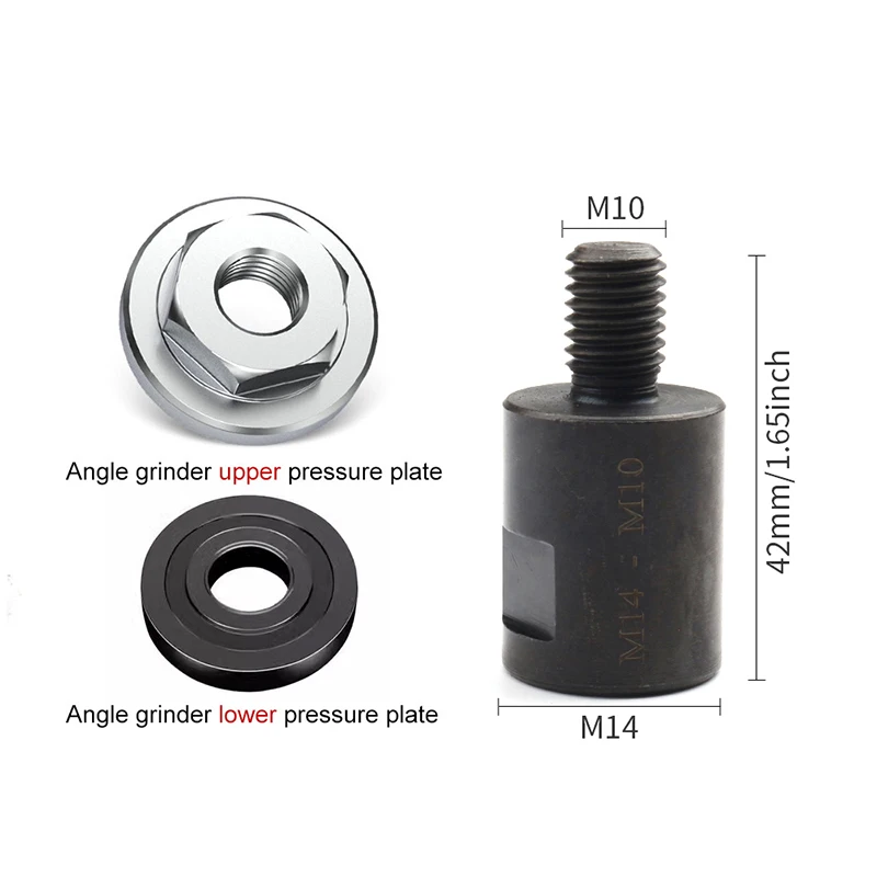
Angle grinders come with two primary thread size standards that determine compatible accessories. Smaller 4½-inch grinders typically use M10 threads (10mm diameter), while larger 9-inch models use 5/8″-11 threads (imperial measurement). Identifying your grinder’s thread size prevents dangerous mismatches – attempting to force a disc with incompatible threading can strip threads and create hazardous mounting situations. The thread size is usually stamped near the spindle, but if unclear, measure the spindle diameter with calipers for accurate identification.
Nut Types and Proper Tightening Techniques
Spindle nuts come in several varieties, each requiring specific tightening approaches. Standard hex nuts require a wrench of the proper size, while some professional models feature quick-change systems with specialized nuts. When identifying your nut type, examine whether it has standard flats for a wrench or special notches for a dedicated tool. Regardless of type, always tighten spindle nuts to manufacturer specifications – typically requiring 25-35 ft-lbs of torque. Under-tightening risks disc ejection, while over-tightening can damage spindle threads. Use your grinder’s spindle lock during tightening, but apply force gradually to avoid shock loading the threads.
Maintenance Points You Should Check Regularly
Proper maintenance extends your angle grinder’s life and prevents dangerous failures. Knowing these labeled parts helps you establish an effective maintenance routine.
Ventilation Slots: Keeping Your Grinder Cool
All angle grinders feature strategically placed ventilation slots that allow cooling air to circulate around the motor. These slots typically appear as multiple narrow openings around the motor housing. When inspecting your grinder, ensure these vents remain clear of dust and debris buildup. Restricted airflow causes dangerous overheating that can melt internal components and create fire hazards. Clean vents regularly with a soft brush – never use compressed air that could force debris deeper into the motor housing.
Mounting Points for Auxiliary Handles
Most angle grinders include one or more mounting points for auxiliary side handles that improve control during demanding operations. These typically appear as threaded holes on the gear case or body housing. When identifying your handle mounting points, check for any stripped threads that would prevent secure handle attachment. Never operate a grinder requiring a side handle without one properly installed – this significantly increases the risk of kickback injuries during aggressive grinding operations. Replace damaged mounting points immediately rather than attempting makeshift solutions.
Final Note
Understanding these labeled angle grinder parts transforms how you maintain, troubleshoot, and safely operate this powerful tool. By recognizing each component’s function and condition, you can prevent dangerous failures before they occur and extend your grinder’s service life significantly. Establish a regular inspection routine focusing on the critical components we’ve covered, and always verify safety features function properly before each use. When replacement becomes necessary, knowing the exact part names ensures you order correct components that maintain your tool’s engineered safety standards. For model-specific diagrams, consult your manufacturer’s official parts breakdown rather than generic illustrations, as small variations between models can affect compatibility and safety.