Your bench grinder won’t start, and you’re staring at a confusing tangle of wires inside the housing. Understanding bench grinder electrical schematics transforms this intimidating scenario into a manageable repair project. Unlike three-phase motors that generate natural rotation, single-phase induction motors in bench grinders require specialized starting mechanisms because they produce only an oscillating magnetic field with no inherent rotational momentum. This fundamental limitation necessitates auxiliary circuitry involving start capacitors, relay mechanisms, and run capacitors working together precisely. Whether you’re troubleshooting a non-starting motor, bypassing failed speed controls, or simply trying to understand why your grinder behaves the way it does, this guide provides the technical knowledge required to confidently interpret and work with bench grinder electrical schematics.
Why Your Bench Grinder Won’t Start: Klixon Relay Operation
The Klixon relay serves as an electromechanical starting switch that eliminates traditional centrifugal switches in many bench grinder designs. This clever system automatically disconnects the start winding once proper operating speed is achieved, protecting your motor from damage.
How Klixon Relays Activate During Startup
When you flip your grinder’s power switch, current flows through both the main motor winding and the relay coil simultaneously. This initial surge creates a strong magnetic field within the relay coil that lifts the armature, closing the start contacts and connecting the start winding to the circuit. With both windings energized, your grinder produces the rotating magnetic fields needed to generate substantial starting torque. This critical phase shift creates the rotational force your single-phase motor needs to overcome inertia and begin spinning.
When the Relay Fails to Disconnect the Start Winding
As your grinder accelerates toward operating speed, current through the main winding decreases proportionally. When this current drops below a calibrated threshold, the magnetic force can no longer maintain armature engagement. If your Klixon relay fails to “drop out” and disconnect the start winding, your start capacitor and winding will overheat rapidly. You’ll notice symptoms like burning smells, excessive heat near the motor housing, or a humming sound without rotation. Never bypass this safety mechanism—a failed relay requires immediate replacement to prevent motor damage.
Dayton 6-Inch Grinder: Decoding the Electrical Layout

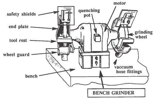
Dayton’s 6-inch bench grinder uses a 1/3 horsepower motor with components strategically housed within the base for serviceability. Understanding this specific configuration helps you interpret similar systems across different brands.
Start vs. Run Capacitor Functions
Your Dayton grinder employs two distinct capacitors working together: the start capacitor (typically 100-300 microfarads) provides high initial capacitance for starting torque, while the run capacitor (10-50 microfarads) operates continuously to improve running efficiency. The start capacitor connects only during startup through the Klixon relay and must disconnect once the motor reaches speed—leaving it energized causes rapid overheating. Visually inspect both capacitors for telltale signs of failure: bulging ends, leaking electrolyte, or discoloration around the terminals.
Relay Coil Current Dependency Explained
The Dayton system’s brilliance lies in its self-regulating nature—the Klixon relay’s operation depends directly on main winding current. This means your relay automatically compensates for voltage fluctuations and load conditions without manual adjustment. When troubleshooting, check for proper relay coil resistance (typically 5-20 ohms) and verify the relay clicks audibly during startup and cutoff sequences. If you don’t hear this distinctive “click-clack” during operation, your relay has likely failed.
Fixing Craftsman Speed Control Failures Permanently
Craftsman 8-inch bench grinders incorporate variable speed circuitry that often becomes the weakest link in the electrical system. When this board fails, you face three options: replace the entire board (expensive), attempt component-level repair (difficult), or bypass to single-speed operation (reliable).
Identifying Speed Control Board Failure Symptoms
Your Craftsman grinder’s speed control is failing if you experience:
– Motor running only at full speed regardless of knob position
– Intermittent operation with sudden speed changes
– Burning smells coming from the control housing
– Visible damage like bulging capacitors or charred circuit traces
Before bypassing, verify power reaches the control board using a multimeter. If voltage appears at the input but not the output, your board has failed and requires replacement or bypass.
Single-Speed Bypass Installation Steps
- Disconnect power and discharge all capacitors using a resistor
- Trace wires from the motor terminals back to the control board
- Identify input (power source) and output (motor) connections
- Install a 15-20 amp toggle switch rated for motor load
- Connect switch directly between incoming power leads and motor windings
- Secure all connections with properly sized wire nuts or terminal blocks
This modification restores reliable operation at your grinder’s rated speed (typically 3,450 RPM) while eliminating the most common failure point in Craftsman grinders. While you lose speed adjustability, most grinding tasks benefit from consistent, maximum RPM operation.
Finding Jet Tools Wiring Diagrams Quickly
Jet Tools’ JBG series (6A, 8A, and 10A models) each have unique electrical configurations documented in official wiring diagrams. Knowing where to find these resources saves hours of guesswork during repairs.
Model-Specific Schematic Requirements
Never assume wiring diagrams are interchangeable between Jet models—even small differences in motor size require different capacitor values and relay configurations. Locate your exact model number on the metal nameplate attached to the motor housing before searching for schematics. Using incorrect documentation risks improper repairs and potential safety hazards.
Authorized Parts Lookup Process
Access genuine Jet Tools schematics through:
– Official dealer networks
– Manufacturer parts lookup portals
– Authorized service centers
– Reputable parts suppliers with direct manufacturer relationships
When ordering replacement components, always reference the part numbers from these official diagrams rather than attempting visual identification—many electrical components look identical but have critical specification differences.
Bench Grinder Electrical Components Decoded
Understanding each component’s function within the electrical system transforms confusing wiring into a logical circuit you can troubleshoot confidently.
Power Cord Safety Inspection Checklist
Your grinder’s power cord requires regular inspection for:
– Cuts or abrasions in the insulation
– Crushed or flattened sections
– Loose connections at plug or terminal points
– Exposed conductors near strain relief points
Replace damaged cords immediately using manufacturer-specified replacements. Never bypass the grounding connection—this critical safety feature protects you from electrical shock during internal faults.
Capacitor Testing Procedure
- Discharge capacitors using a 10k-20k ohm resistor
- Set multimeter to capacitance measurement mode
- Disconnect one lead from the capacitor
- Connect meter probes to capacitor terminals
- Compare reading to rated value (±10% acceptable)
Failed capacitors often cause hard starting conditions, reduced power, or complete failure to start. Replace any capacitor outside acceptable tolerance ranges.
Reading Bench Grinder Schematics Like a Professional
Electrical schematics use standardized symbols that, once understood, reveal the complete operational logic of your grinder’s electrical system.
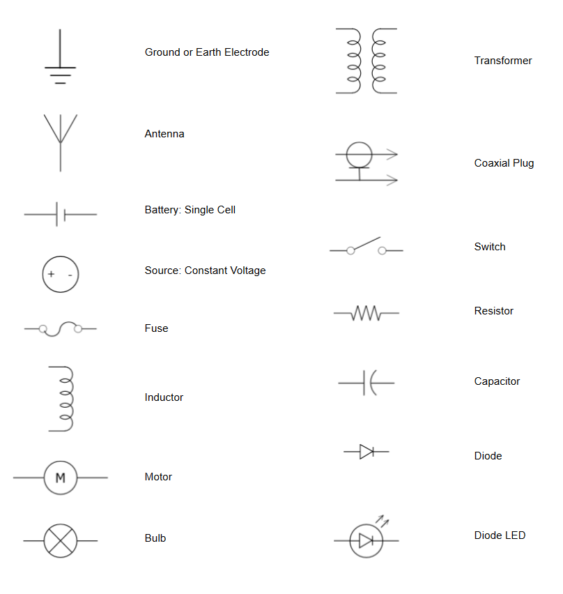
Critical Symbol Recognition Guide
- Motor windings: Represented as coils labeled “Main” and “Start”
- Capacitors: Two parallel lines of unequal length
- Relay contacts: Switch symbols with dashed lines indicating mechanical linkage
- Ground connections: Three horizontal lines decreasing in size (earth ground)
When tracing circuits, follow current flow from power input through protective devices, switching mechanisms, and finally to the motor windings. Note how control circuits interact with power circuits—this relationship explains how your grinder’s operational states change.
Troubleshooting Common Electrical Failures
Electrical problems in bench grinders follow predictable patterns that point directly to specific component failures.
Motor Won’t Start: Diagnostic Flow
- Verify power at the outlet with a multimeter
- Check cord continuity from plug to motor terminals
- Bypass the power switch with a jumper wire
- Inspect and test start capacitor
- Verify Klixon relay operation (listen for clicks)
- Check thermal overload reset button
This systematic approach isolates the problem to one specific component without unnecessary part replacement.
Intermittent Operation Fixes
Loose connections cause most intermittent issues. Tighten all terminal screws and inspect wire connections for:
– Corrosion or oxidation on contact surfaces
– Broken strands in wire conductors
– Insulation damage causing intermittent shorts
– Thermal cycling damage at connection points
Clean affected terminals with electrical contact cleaner and resecure connections with proper torque.
Essential Safety Steps Before Electrical Work
Working with bench grinder electrical systems requires strict safety protocols to prevent injury.
Mandatory Pre-Work Procedures
- Always disconnect power at the source before opening the housing
- Verify no voltage present using a properly rated multimeter
- Discharge all capacitors through appropriate resistors (never short terminals)
- Use insulated tools rated for electrical work
- Work in a clean, dry environment free of conductive debris
Capacitors retain dangerous charges even after power disconnection—treat every component as live until personally verified otherwise. If you’re uncertain about any procedure, consult a qualified electrician rather than risking injury.
Understanding bench grinder electrical schematics gives you the power to maintain, troubleshoot, and repair your equipment confidently. By recognizing component functions, interpreting wiring diagrams, and following systematic diagnostic procedures, you transform confusing electrical systems into manageable repair projects. Whether you’re working with Dayton’s Klixon relay system, bypassing Craftsman speed controls, or interpreting Jet Tools diagrams, this knowledge ensures your bench grinder remains a reliable workshop tool for years to come. Keep this guide handy for your next electrical repair, and always prioritize safety when working with live circuits.