Your bench grinder suddenly stops working, and you suspect an electrical issue. Before replacing the entire unit, understanding the grinder motor wiring diagram could save you time, money, and frustration. Proper wiring ensures your grinding equipment operates safely and efficiently while preventing dangerous electrical hazards. Whether you’re troubleshooting a humming motor that won’t start, replacing a failed capacitor, or installing a new motor in your workshop, this guide provides the specific wiring knowledge you need. You’ll learn to interpret wiring diagrams, make correct connections for both 120V and 240V systems, and safely address common electrical problems in single-phase grinder motors.
Identifying Critical Grinder Motor Electrical Components
Before connecting any wires, you must recognize the essential electrical components inside your grinder motor. Each element plays a specific role in starting and maintaining motor operation, and knowing their functions prevents dangerous wiring mistakes.
Start and Run Windings Explained
Your grinder motor contains two distinct winding sets: the run winding (main winding) and the start winding (auxiliary winding). The run winding connects directly to power and maintains continuous rotation once the motor starts, while the start winding provides the initial torque needed to overcome inertia. These windings create a phase-shifted magnetic field that generates rotational force—without both functioning correctly, your grinder won’t start or will overheat during operation.
Capacitor Functions and Types
Single-phase grinder motors require capacitors to create the necessary phase shift for starting. The start capacitor (typically 50-1000 μF) connects in series with the start winding and provides high initial torque. Once the motor reaches approximately 75% of operating speed, the centrifugal switch disconnects this capacitor to prevent overheating. Some motors also include a run capacitor (2-80 μF) that remains connected during operation to improve efficiency and torque. Recognize start capacitors by their black rubberized housing (intermittent duty rating) versus run capacitors with metal or hard plastic housings (continuous duty).
Interpreting Grinder Motor Wiring Diagram Symbols

Wiring diagrams use universal symbols that you must understand to make correct connections. Misreading these symbols can lead to reversed rotation, motor damage, or electrical hazards.
Essential Symbol Recognition
When examining your grinder motor wiring diagram, identify these critical symbols:
– Motor windings appear as coiled lines, with run windings typically thicker than start windings
– Capacitors show as two parallel lines (one solid, one broken)
– Centrifugal switches display as normally-open contacts that close when stationary
– Ground connections feature three horizontal lines decreasing in size
– Junction dots indicate wire connections (no dot means wires cross without connecting)
Terminal Block Configuration
Your motor’s terminal box contains numbered connection points that correspond to the wiring diagram. Common terminal designations include:
– L1/L2: Line power connections (120V/240V)
– T1/T2: Main winding terminals
– T5/T8: Start winding terminals
– C: Capacitor connection point
– OL: Overload protector terminals
Always verify terminal numbers against your specific motor diagram—using incorrect terminals can damage windings or create shock hazards.
Connecting a 120V Single-Phase Grinder Motor
Most workshop bench grinders operate on standard 120V household current, but wiring them correctly requires understanding the specific circuit configuration.
Basic 120V Wiring Sequence
Follow these steps to wire your 120V grinder motor safely:
1. Disconnect all power at the circuit breaker and verify with a voltage tester
2. Connect the black (hot) wire to one side of the thermal overload protector
3. Attach the other overload terminal to L1 (Line 1) on the motor
4. Connect the white (neutral) wire directly to L2 (Line 2)
5. Join the green grounding wire to both the motor frame and electrical system ground
6. Wire the start capacitor between the start winding and centrifugal switch
Critical warning: Never connect neutral to the motor frame—this creates an immediate shock hazard. The green grounding wire must connect to a dedicated grounding terminal, not a neutral point.
Centrifugal Switch Verification
Before applying power, test your centrifugal switch with an ohmmeter:
– With the motor shaft stationary, you should measure continuity across the switch terminals
– When rotated by hand, the switch should open at approximately 75% of operating speed
– A switch that remains closed prevents the start capacitor from disconnecting, causing rapid overheating
Converting to 240V for Improved Performance
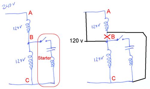
Upgrading to 240V reduces current draw by half, minimizing voltage drop on long circuit runs and improving motor performance under heavy grinding loads.
Dual-Voltage Wiring Procedure
To convert your grinder motor to 240V operation:
1. Disconnect power and remove the terminal cover
2. Reconfigure internal windings from parallel (120V) to series (240V) connection
3. Connect both hot wires (black and red) to L1 and L2 terminals
4. Leave the neutral wire disconnected (240V circuits don’t use neutral)
5. Maintain the grounding connection to the motor frame
Pro tip: After conversion, verify voltage at the motor terminals under load—voltage should remain within 10% of rated value. Significant voltage drop indicates undersized wiring that needs upgrading.
Reversing Motor Rotation for Special Applications
Some grinding tasks require clockwise rotation while others need counterclockwise—understanding reversible motor wiring solves this problem without mechanical modifications.
DPDT Switch Installation
To wire a reversible grinder motor:
1. Install a double-pole, double-throw (DPDT) switch rated for 125% of motor amperage
2. Connect line power to the center terminals of the DPDT switch
3. Wire one set of outer terminals to the run winding ends
4. Connect the other outer terminals to the start winding through the centrifugal switch
5. Position the switch so center position is “OFF” with rotation directions on either side
Never attempt: Changing direction while the motor runs—always allow complete stoppage before switching. Attempting live switching causes severe arcing that destroys switch contacts and creates fire hazards.
Troubleshooting Common Wiring Failures

Most grinder electrical problems stem from three common wiring issues that you can diagnose with basic tools.
Motor Humming Without Starting
When your grinder hums but won’t rotate:
– Check centrifugal switch continuity with motor stopped (should show closed circuit)
– Test start capacitor with multimeter (reading should be within 10% of labeled μF)
– Verify start winding resistance (should measure 10-50 ohms, significantly higher than run winding)
– Rotate grinding wheel by hand—if it starts, your start circuit is faulty
Overheating Motor Solutions
If your grinder motor overheats during normal operation:
– Measure voltage at motor terminals under load (low voltage causes excessive current draw)
– Check run capacitor functionality (failed run capacitors cause 20-30% power loss)
– Inspect for loose connections in terminal box (vibration causes gradual loosening)
– Verify adequate ventilation around motor (blocked cooling vents cause rapid overheating)
Critical mistake to avoid: Ignoring frequent thermal overload trips—this indicates either excessive grinding pressure, electrical problems, or failing windings that require professional diagnosis.
Essential Safety Grounding Procedures
Improper grounding causes more electrical accidents than any other single factor in workshop equipment.
Grounding Verification Steps
Before operating your wired grinder:
1. Confirm green grounding wire connects directly to motor frame terminal (not neutral)
2. Test continuity between motor housing and electrical panel ground bus
3. Verify ground resistance measures less than 1 ohm with a dedicated tester
4. Install GFCI protection for all workshop grinders (required within 6 feet of water sources)
Safety imperative: Never remove the grounding pin from the power plug or use adapters that bypass grounding—this eliminates your primary protection against lethal shock if internal wiring fails.
Capacitor Replacement Best Practices
Capacitors fail more frequently than any other grinder motor component, but proper replacement prevents repeated failures.
Correct Capacitor Selection
When replacing capacitors:
– Match microfarad (μF) rating within 5% of original specification
– Use voltage rating equal to or higher than original (never lower)
– Select correct duty type (start capacitors have intermittent duty rating)
– Verify physical size fits within terminal enclosure
Pro tip: Before handling failed capacitors, discharge them by connecting a 20kΩ resistor across terminals for 30 seconds—capacitors can store lethal voltage even when disconnected.
Final Wiring Verification Checklist
Before applying power to your wired grinder motor:
– Confirm all wire connections are tight (vibration loosens terminals)
– Verify no stray wire strands could cause shorts
– Check for damaged insulation near sharp metal edges
– Ensure centrifugal switch operates freely
– Confirm grounding connection to motor frame
When to call a professional: If you’re uncertain about any connection, consult a qualified electrician—improper wiring can cause fire, equipment damage, or lethal shock. Never operate a grinder with questionable electrical connections.
Maintenance reminder: Inspect your grinder motor wiring annually for loose connections, damaged insulation, and capacitor bulging. Clean dust from ventilation slots monthly to prevent overheating. Proper electrical maintenance extends motor life by 3-5 years while ensuring safe operation in your workshop. Always disconnect power before performing any electrical work on grinding equipment.