
Your bench grinder’s electrical system has stopped working, and you’re staring at a tangle of wires with no idea where to begin. Without the correct bench grinder electrical schematics, even replacing a simple switch becomes a dangerous guessing game. Finding and understanding your specific wiring diagram is the critical first step to safe, effective repairs that restore your grinder’s performance without risking electrical hazards.
Many workshop accidents happen when DIYers attempt electrical repairs without proper documentation. Bench grinders contain high-current circuits where a single misplaced wire can create fire risks or shock hazards. Jet Tools models like the JBG-6A, JBG-8A, and JBG-10A each have unique electrical configurations that require their specific schematics for accurate repairs. This guide shows you exactly how to locate your model’s wiring diagram, interpret the symbols, and apply the information safely to fix common electrical issues.
Identify Your Bench Grinder’s Electrical Components Before Troubleshooting
Before you can read a schematic, you need to know what components actually exist in your bench grinder’s electrical system. The motor assembly contains the most critical elements that determine how your grinder starts and runs. Most bench grinders use a capacitor-start motor design that relies on a start capacitor to provide the initial torque needed to overcome rotational inertia. This component works only during startup and disconnects once the motor reaches operating speed.
The centrifugal switch inside the motor housing automatically disconnects the start capacitor circuit once the motor reaches sufficient RPM. This switch prevents the start capacitor from overheating during continuous operation. When this switch fails, your grinder might hum but won’t spin up to full speed. Run capacitors, when present in your model, remain in the circuit during operation to improve efficiency and reduce vibration.
Thermal overload protection serves as your safety net against motor burnout. This component monitors temperature and interrupts power when dangerous conditions develop. Bench grinders typically feature either automatic reset overloads that cycle on and off or manual reset types requiring intervention after tripping. Your electrical schematics will specify the exact amperage rating for replacement overloads.
Power distribution components include:
– The on/off switch assembly with safety interlocks
– Power cord with proper grounding conductor
– Strain relief connections securing wires at entry points
– Internal wiring harnesses connecting components
– Terminal blocks where motor connections terminate
Find Your Exact Bench Grinder Wiring Diagram in 4 Steps
Locating your specific bench grinder electrical schematics begins with identifying your model number from the nameplate. This metal tag appears on the motor housing or base of your grinder and contains critical information. For Jet Tools models, look for designations like JBG-6A (6-inch), JBG-8A (8-inch), or JBG-10A (10-inch) along with part number 577101.
Access manufacturer documentation through these verified channels:
-
Authorized dealer websites like Jack’s Small Engines provide reliable parts lookup systems. Navigate to the manufacturer section, select Jet Tools, choose “Grinder” or “Bench Grinder” as the tool type, then enter your specific model designation.
-
Manufacturer customer service departments often provide schematics upon request. Call with your model and serial numbers ready—they may email PDF documentation or direct you to online resources.
-
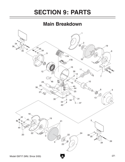
Parts diagrams serve as valuable companions to wiring schematics. These illustrations identify components by number, helping you match physical parts to their schematic representations. The Jet Tools parts list documentation shows each electrical component’s position and connection points.
-
Model-specific portals sometimes require registration but offer complete service manuals. Search for “Jet Tools service manual JBG-8A” rather than generic terms to reach the correct documentation.
Why Generic Wiring Diagrams Won’t Work for Your Grinder
Using a generic or incorrect bench grinder electrical schematics creates dangerous risks. A 6-inch Jet JBG-6A grinder uses different capacitor ratings than the 8-inch JBG-8A model. The centrifugal switch configuration varies between models, and thermal overload specifications differ based on motor horsepower. Attempting repairs with mismatched documentation can lead to:
- Overheating from incorrect capacitor values
- Motor failure due to improper voltage application
- Safety hazards from bypassed protection circuits
- Permanent damage to expensive motor windings
Decode Bench Grinder Schematic Symbols Like a Professional

Electrical schematics use standardized symbols that represent real-world components. Learning these symbols transforms confusing diagrams into clear repair roadmaps. Motor windings appear as zigzag lines or coil symbols, with start and run windings shown separately. Capacitors display as parallel plate symbols—round for start capacitors and rectangular for dual-run types.
Critical Symbols to Recognize Immediately
- Centrifugal switch: Shown as a normally-closed contact that opens at speed, often drawn with a curved arrow indicating rotational activation
- Thermal overload: Represented by a rectangle with a curved line inside, always positioned in series with the motor windings
- Capacitors: Parallel lines with optional polarity markers; start capacitors connect through the centrifugal switch
- Ground connections: Three horizontal lines decreasing in size or the universal ground symbol
Trace current flow from the power source through the switch, overload protection, centrifugal switch, capacitors, and into the motor windings. Bench grinder schematics typically arrange components with power entering at the top or left, flowing toward the motor load at the bottom or right. This convention helps you follow the circuit path logically rather than jumping randomly between sections.
Apply Schematic Knowledge to Fix Common Electrical Failures
When your bench grinder won’t start but makes a humming sound, your bench grinder electrical schematics reveal the likely culprit: a failed start capacitor or malfunctioning centrifugal switch. Follow these steps using your specific diagram:
- Locate the start capacitor on your schematic (usually labeled C1 or similar)
- Disconnect power and safely discharge the capacitor
- Test capacitance with a multimeter—values below 80% of rated capacity require replacement
- Verify centrifugal switch continuity with the motor shaft rotated to simulate startup speed
Troubleshoot Complete Power Loss Systematically
No power at all? Your schematic guides this diagnostic process:
- Check for voltage at the switch input terminals with power applied
- Test switch output with the grinder turned on—if no voltage, replace the switch
- Verify continuity through the thermal overload protector
- Follow the schematic trace to the motor terminal block, checking each connection point
Implement Critical Safety Protocols Before Touching Any Wires

Working with bench grinder electrical systems demands strict safety practices that prevent shocks and fires. Never assume the circuit is dead—always verify with a multimeter rated for the voltage you’re working with. Bench grinders typically operate on 120V circuits capable of delivering lethal current.
Disconnect the power cord completely before beginning work. In shared workshops, apply a lockout/tagout device to the power source to prevent accidental re-energizing. Test all circuits with your multimeter before touching any components—many electrical injuries occur when technicians skip this critical verification step.
Grounding verification proves essential for safe operation. Your bench grinder electrical schematics shows the ground path from the power cord through the motor housing. After any repair, perform a continuity test between the ground pin of the plug and exposed metal parts of the grinder. Resistance should measure less than 1 ohm—higher values indicate a compromised ground path that creates shock hazards.
Maintain Your Grinder’s Electrical System Proactively
Prevent electrical failures before they happen with these maintenance practices:
- Inspect power cords monthly for cuts, fraying, or damaged strain relief
- Clean switch assemblies annually with electrical contact cleaner
- Test start capacitors every 6 months for capacitance drift
- Check terminal block connections for tightness during routine maintenance
Capacitors showing bulging cases, leaking electrolyte, or raised vents require immediate replacement. Don’t wait for complete failure—they can fail catastrophically, potentially damaging other components. When replacing capacitors, always match the microfarad (µF) rating and voltage specification shown on your bench grinder electrical schematics.
Access Documentation Resources Without Manufacturer Delays
Create a documentation system that puts your bench grinder electrical schematics at your fingertips:
- Photograph the nameplate showing model and serial numbers before they become unreadable
- Store digital copies of wiring diagrams in a dedicated workshop folder
- Bookmark the specific parts lookup page for your model on Jack’s Small Engines
- Keep a printed copy of your schematic inside the grinder’s housing compartment
When seeking replacement parts, always reference the component numbers from your parts diagram rather than describing parts verbally. A Jet Tools JBG-8A grinder might use capacitor part number JC-450-8, while the JBG-6A uses JC-450-6—the difference matters for proper function and safety.
Final Verification Steps Before Powering Up Repairs
Never skip these critical checks after completing electrical repairs:
- Double-check all wire connections against your bench grinder electrical schematics
- Confirm no tools or debris remain inside the motor housing
- Verify ground continuity measures less than 1 ohm
- Perform a visual inspection of all components for proper seating
When in doubt about any connection, consult the manufacturer’s documentation again rather than guessing. A few extra minutes of verification prevent costly mistakes and dangerous malfunctions. Your Jet Tools JBG-10A grinder’s electrical system will reward careful attention with years of reliable service when maintained using the correct schematics and procedures.